In this section, i will explain how to build the Tools , the tool holder , and what is the principle of calibration for these Tools .
There is one section per tool, but please read the "before you start" section to understand what are the prerequisites for your own printer.
Before You start
Tool Holder
Pen
Marker
Scratcher
PCBDrill
You can also have a look immediately on how these Tools will be used in the section :
Make PCBs
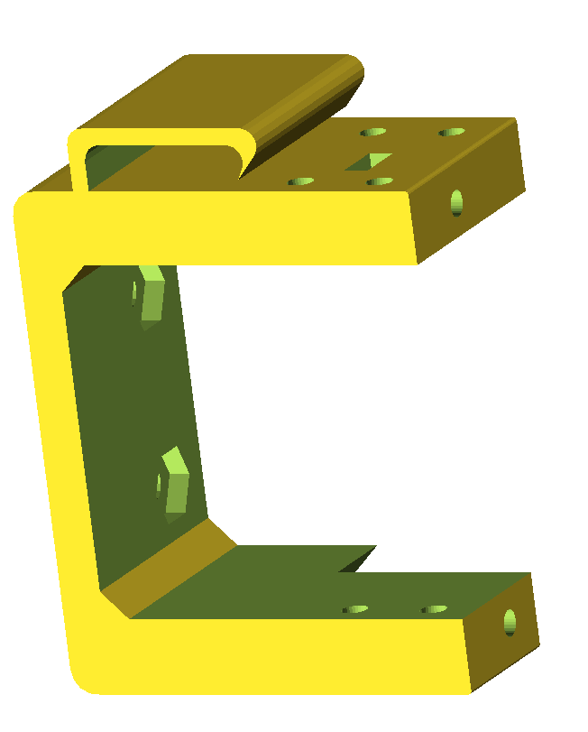
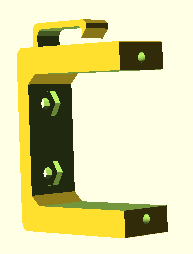
In order to build the Tools, you will need the following 3D files :
Fix support for emotiontech prusa 1.5 :
Standard support for Nema 17 (not tested... ) :
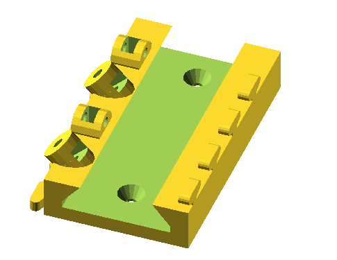
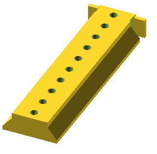
Multi tool Rail :
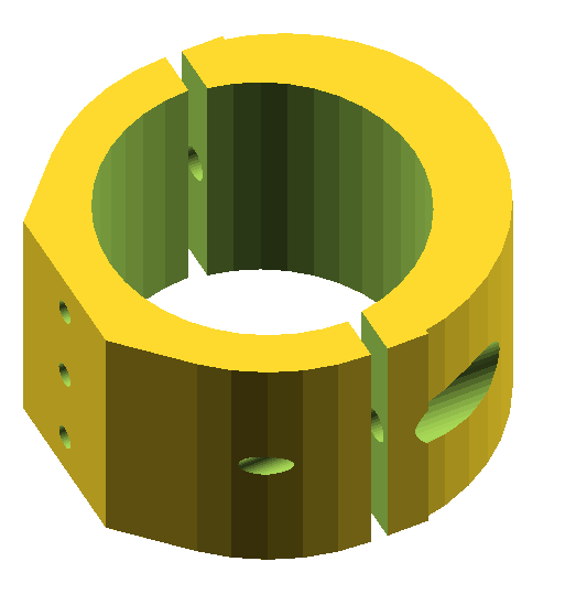
and an optional knob for the adjustment screws
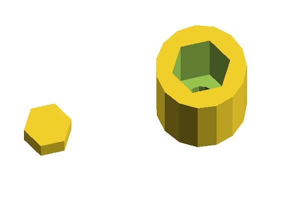
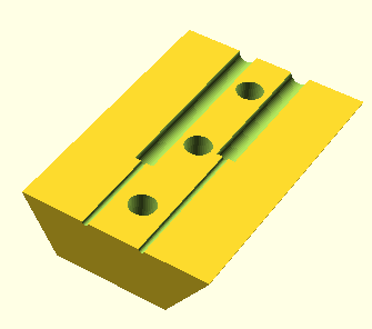
Customizable Slider for the Rail
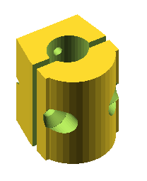
Cylindric Tool Holders ( diameters from 6 to 16 )
needle holder : ( to be printed twice )
Designed for use with sewing machine needles ( special Jeans)
You can use standard wood screws to build the Tools.
You can download all the stl files from the thinggiverse post :
https://www.thingiverse.com/thing:2415508
Now that you have a nice pcb, with tracks in copper, you will want to drill it :
Be sure to use carbid drill bits. I tried with standard hardware drill bits, and they are just able to perform 10 to 20 drills until they no longer drill anything !
In order to drill the pcb, you can use the following process :
Place your copper clad on the printed support, usually you would put it with the top side visible.
Test the gcode in test mode :
Mount the drill tool in sliding mode ( for testing).
Ensure that the drill tool can slide vertically freely.
Do not turn on the drill tool : the dril tool will therefore touch the pcb without drilling anything.
Launch the drill gcode for each diameter.
Output\7_drill\drill_Top_0.xx_drill_+_data.gcode
Output\7_drill\drill_Top_0.yy_drill_+_data.gcode
Output\7_drill\drill_Top_0.zz_drill_+_data.gcode
Verify that the drill tool touches the pcb at the right position, precisely.
Re-perform Calibration in case the drill position is not exact :
Use the “P0 position” on the support to perform the Calibration.
Remember to always rerun the generategcode.vbs script after each calibration change.
Once you are happy that the drill tool is moved accurately to the correct positions, you are ready to drill in real mode.
Drill for real :
Fix the drill tool on the slider , so that the drill tool no longer slides vertically.
Ensure you set the correct size for the drill bit
Then Launch the drill gcode for each diameter, by changing the drill bit accordingly.
Output\7_drill\drill_Top_0.xx_drill_+_data.gcode
Output\7_drill\drill_Top_0.yy_drill_+_data.gcode
Output\7_drill\drill_Top_0.zz_drill_+_data.gcode
That s it ….
Once the tracks are printed on the coper, you can etch the copper with your etchant solution, then clean the copper with acetone.
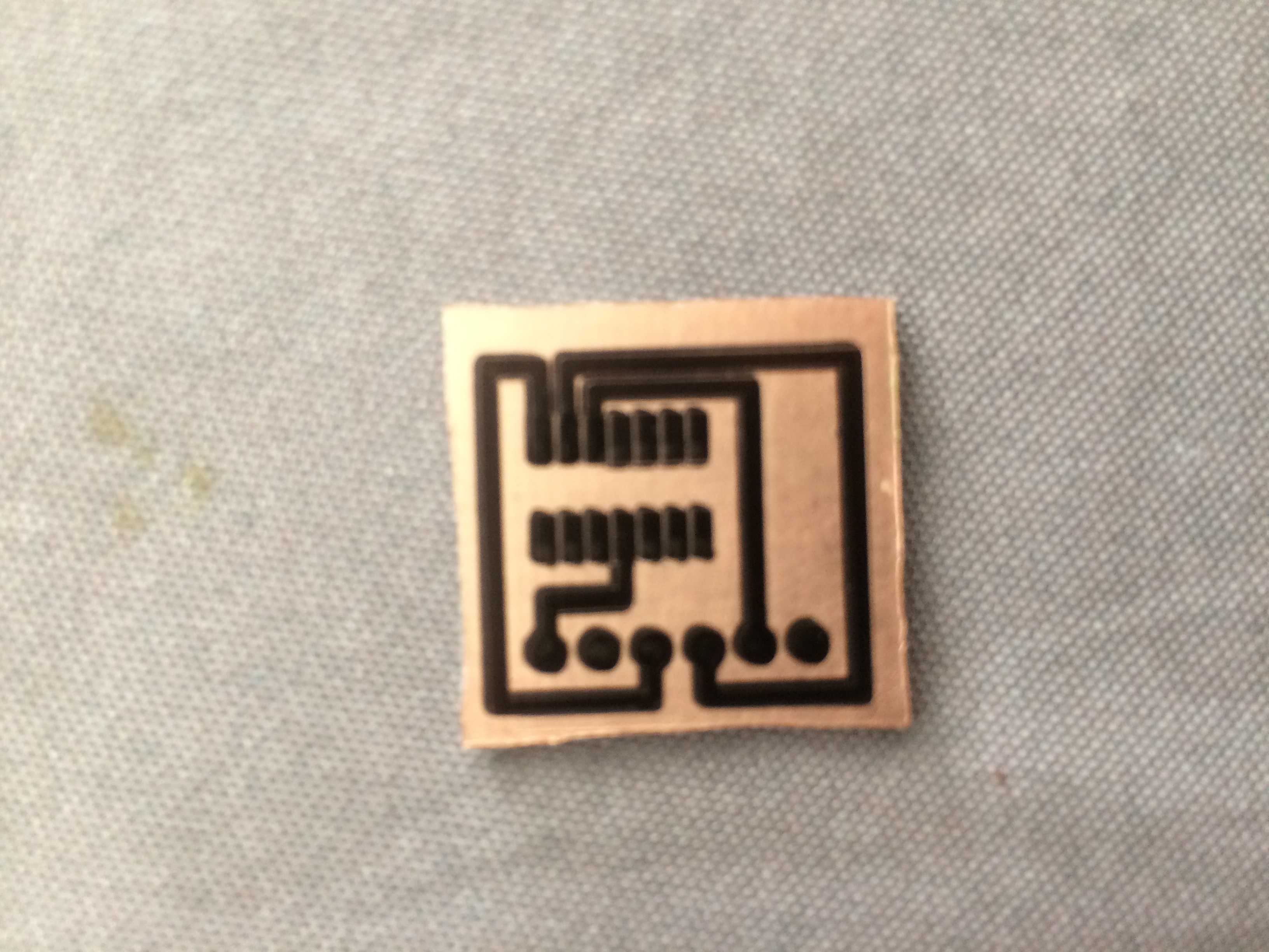
A small circuit to hold a SOIC component.
There are many tutorials on internet on how to perform this specific phase of the process, so I am not going to add some more here…
I used below the etch resist pen from Shaedtler, 0.6mm. ( i believe there is also a Shaedtler 0.4mm , but i did not tried it)
The tracks are not perfect, but are working. Some better results would be obtained with the insolation method.
- You are here:
-
Home

-
Download
-
Download 3D files
- Uncategorised